Welcome: ColorSpace 400-886-3881 400-886-3381
Language:
 ∷
∷

∷
∷


Summary
The advanced driver assistance system (ADAS) based on the camera application needs to map the image coordinates to the known world coordinate system, and the process of calculating the mapping is geometric calibration. This article provides a series of tests that can be used to evaluate the advantages of geometric correction and compare different verification methods:
1. Image coordinate system test: verify that different imaging systems use the same image coordinates.
2. Re-projection test: Project the target to the image surface through the model to verify the calibration of the camera.
3. Projection test: Verify the calibration of the camera by back-projecting the points in the model onto the world.
4. Triangulation test: to verify the ability of the multi-camera system to locate a point in 3D.
This article will introduce the above four verification methods. The first method is to verify that the image coordinates between the two systems are consistent. The remaining methods are to use different methods to verify the consistency of different models and camera performance.
(The potential configurations of these tests are driven by automotive use cases, and different calibration models of the built-in camera can be compared and adjusted)
Introduction
Geometric calibration provides a mathematical model of the pointing direction of each pixel [1, 2] in the camera. The model may or may not have parameters related to the physical parameters of the camera system. For a schematic diagram of the geometric camera model, see Figure 1. The black line in this diagram represents the optical axis.
The geometric calibration of the camera helps to break through the manufacturing tolerance limits, extract more performance from the camera, reduce costs/increase output.
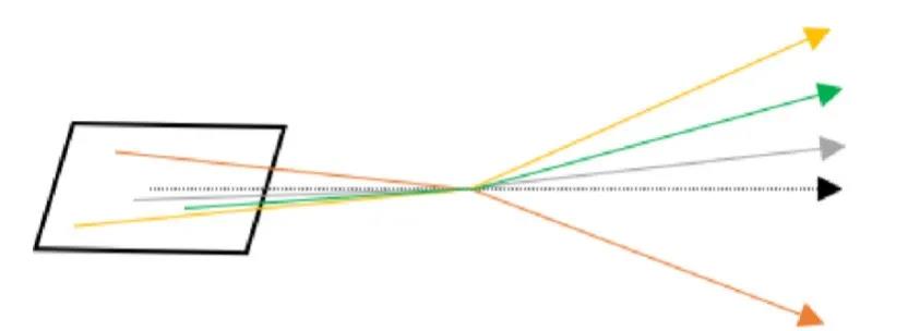
(Figure 1 Schematic diagram of the camera model. The pixel position is mapped to the light entering the world)
Geometric calibration can be used to convert pixel-based metrics to physics-based metrics. One use of geometric calibration is to calculate the projection modulation transfer function (MTF) of the world system, that is, the MTF expressed in world units. The second purpose is to calculate the instantaneous field of view (IFOV) of each pixel, allowing photoelectric or radio calculations.
There are many potential model forms. When a certain model is selected, there are additional degrees of freedom as the parameterization of the model. The range is too large, making it difficult to choose. If possible, creating a standard method to complete a geometric calibration camera will meet the requirements of the ADAS system. In addition, the calibration reference settings and optimization parameters vary with the camera design. Therefore, we turned to developing verification methods to be able to compare camera calibrations of the same camera and ensure that the calibration model meets the requirements of the ADAS system.
I. Image coordinate system verification
Many possible image coordinate systems can be used. Some of them are shown in Figure 2. Even in the same organization, the image coordinates of the two teams may not be the same. One of the teams includes the verification team that is collecting and running other verification tests later in this article. Ensuring that the team knows the different coordinates of its partners will reduce the chance of problems.
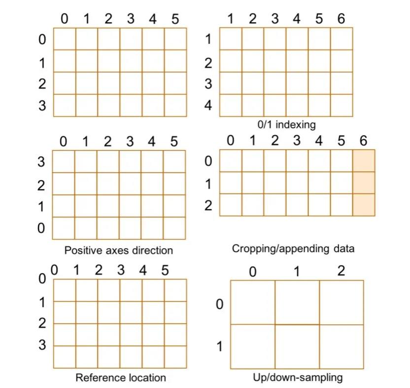
(Figure 2. Possible image coordinate system differences)
The team should at least communicate the coordinate system they use, especially when describing the relative geometric calibration parameters of the sensor (such as principal points and distortion centers). The rest of this section will describe a clear test to determine the conversion between image coordinate systems of different teams.
Method
This method utilizes the sensor test mode. This is a clear reference coordinate system.
1. Generate row index and column index sensor test patterns from the sensor through the acquisition system. For example, through a production line collection system or an engineering collection system. It is important to turn off the image signal processing (ISP), which will prevent the data from being altered and invalidating the test.
2. Among the teams involved, determine at least 3 non-column and non-column reference points in the test mode coordinate system. In other words, each row and each column can only have at most one test point.
3. Find the position of the reference coordinate in the coordinate system. These are image data values.
4. Perform ordinary least squares (OLS) regression for each row and column coordinate. The regression form is: y=m·x+b. Generally speaking, the correlation coefficient of these regressions is exactly 1. In addition, unless there is an UP or Down-sampling model between the two coordinate systems, the slope of the equation will be ±1.
Example
This article takes the coordinate system of the 6×4 image sensor used by the two teams as an example. The position of the mark in each coordinate system is shown in Figure 3. The reference sensor coordinate is the color of the pixel, and the coordinate system of the team is given by the pixel position label. The position of the reference point is listed in the table titled "Position of the point in the example".
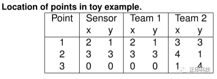
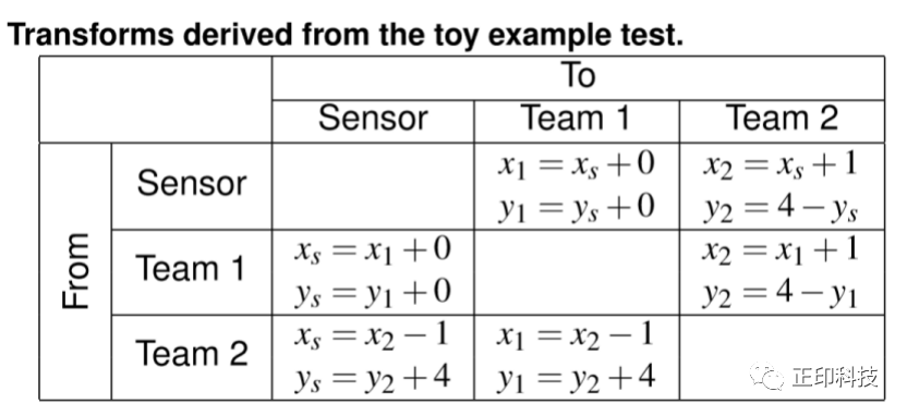
Perform OLS regression on the data in Table 1, and get the coordinate system transformation in the table titled "Transformation Derived from Toy Example Test". Based on the inspection of these results, the first group uses sensor coordinates, while the second group uses a single-index coordinate system with the y-axis flipped. These two are not necessarily wrong, but you need to be careful when communicating between the two teams.
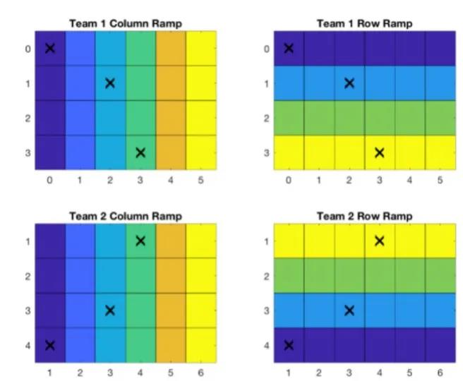
(Figure 3. Example marker points in two team coordinate systems.)
The reprojection test projects the target to the camera model and calculates the error in the image space. This is the same method used to calculate the reprojection error during calibration. The metric is the distance between the detected target position and the modeled target position. Note that the settings should be separate from any calibration to avoid overfitting. Refer to Figure 4 for a schematic diagram of the projection test comparing the detected target position and the modeled target position.
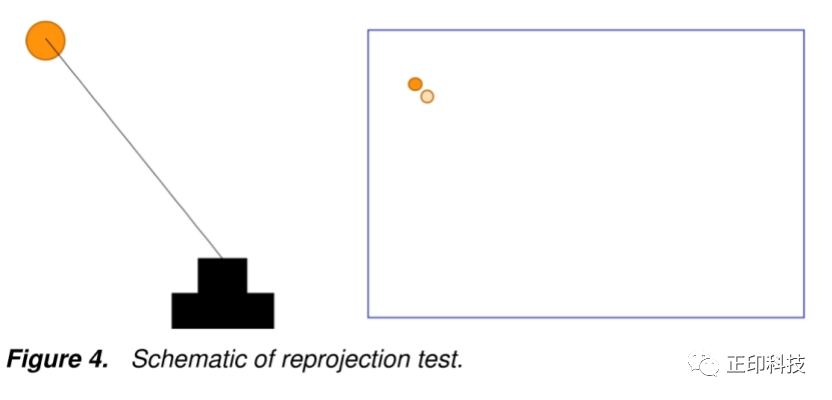
(Figure 4. Schematic diagram of reprojection test)
Method
1. Create a test setup using the targets in the scene.
2. Measure the position (posture) of the target relative to the camera coordinate system.
3. Take an image of the target.
4. Detect the target in the image.
5. Project (imaging direction) the target position through the camera model (step 2).
6. Calculate the error between the detection point and the projection point in the image space (reprojection error).
7. Repeat the operation as needed to ensure test coverage.
III.Projection test
The reprojection test uses the forward or image formation direction of the geometric calibration model, while the projection test uses the reverse projection of rays onto the world. For many calibrations used in ADAS applications, this is a more natural direction. This test assumes that the distance from the camera to a pair of targets is known. The camera relative world point is calculated by projecting the target position in the camera model to a known distance. The test index is the difference between the distance in the projected world point and the distance measured separately between the target.Configuration
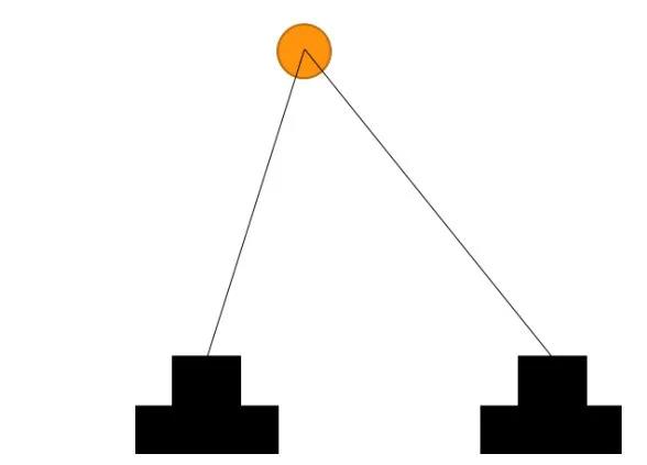
There are two configurations for the projection test. The first configuration model is the Simultaneous Localization Mapping (SLAM) use case. The test has two narrowly spaced targets, a single capture or a pair of capture positions along the camera's direction of travel. Refer to Figure 5 for an example of this configuration.
(Figure 5. SLAM projection test configuration)
The size of relative objects is one of the basis used by the human visual system to determine depth. The second configuration tests the ability to determine the size of an undistorted target object. Refer to Figure 6 for an example of this configuration.
(Figure 6. Object size projection test configuration)
Method
1. Use the target pair in the scene to create a test setup.
2. Measure the distance from the camera to each target.
3. Measure the distance between the target pair.
4. Take an image of the target pair.
5. Detect the target pair in the image.
6. Project the distance from each detected image point to the target into the world (step 2) to generate a world point.
7. Calculate the distance between each pair of projected world points.
8. Calculate the difference between the projection distance (step 7) and the measured target pair distance (step 3).
9. Repeat the operation as needed to ensure test coverage.
IV.Triangulation test
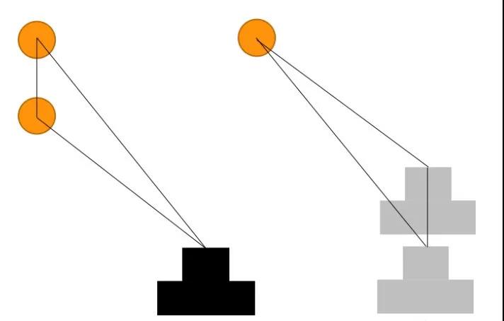
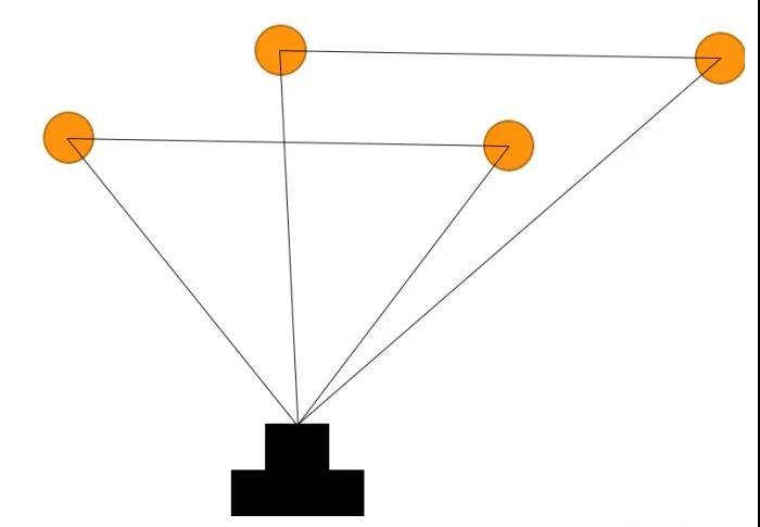
The triangulation test is similar to the reverse projection test using a camera model. The test relies on a single target that can be found in both cameras. Then the image position is converted into a pointing direction, which can be used to triangulate a world point. The metric is the difference between the target measurement position and the triangulation. For a schematic diagram of this test, please refer to Figure 7.
(Figure 7. Schematic diagram of triangulation)
Method
1. Use the target pair in the scene to create a test setup.
2. Measure the position (posture) of the target relative to the reference camera coordinate system.
3. Take the target image with two cameras.
4. Detect the target in the image acquired by each camera.
5. Triangulate the target with the detected points.
6. Calculate the error between the measured position (step 2) and the target triangle position (step 5).
7. Repeat the operation as needed to ensure test coverage.
Verify test configuration
The point of use of "target" and location is abstract and has not yet been defined. This section will introduce in detail the selection and placement of targets in the test scene.
Target selection
See Figure 8 for an example of possible targets. The first two goals are the intersection of the point and the checkerboard. These objectives are used to test situations where full feature detection algorithms (such as convolutional neural networks) are not accessible. The reference positions (measured position/distance from them) of these two targets are the center of the point and the saddle point of the chessboard respectively.
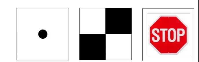
(Figure 8. Possible target choices)
The third objective choice represents the automotive use case objective, such as a stop sign. These targets are intended to be used when testing the entire computer vision system (including cameras and target detection algorithms). The reference position of these targets is the target position located by the computer vision system, for example, the intersection of "T" in "STOP".
Target placement
Two aspects of target placement need to be considered: the distance to any target and the distance between targets. The distance to the target should be determined by the use of the car camera. This can be partially determined by solving the equations for various vehicle speed and time requirements: d=v*t.
In order to make the test as close to the driving conditions as possible, the use of intermediate optics (such as a collimator) for verification tests should be avoided. For projection testing, the distance of the target should also be associated with the automotive use case. The distance configured by SLAM should be related to the frame time t and the frame number n: d=n*v*t.
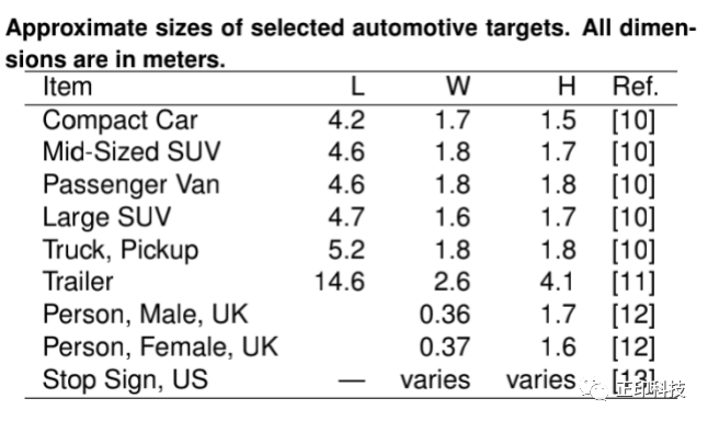
The target distance of the object size test configuration should be related to the size of the object encountered in the driving environment. Some of these dimensions are recorded in a table titled "Approximate Dimensions of Selected Car Targets."
Target coverage
The ensemble test conducted should cover the entire field of work. A single test near the optical axis will not provide any information about the model's performance near the edge of the FOV. Coverage can be obtained by filling the field of view with objects and capturing a single image, or by using a limited number of objects and capturing multiple images. For the latter configuration, rotating the camera around its center (for many camera models, its entrance pupil position on the axis) will reduce the required setup measurement requirements.
Measurement accuracy
Repeat target
It is not recommended to use a single target anywhere. In these configurations, it is impossible to separate measurement errors, target detection errors, and calibration errors. If multiple targets are very close to each other, the above errors can be more easily separated by identifying non-family results. Refer to Figure 9 for an example of using multiple targets in each location. The expected error between any pair of distant groups is the same.
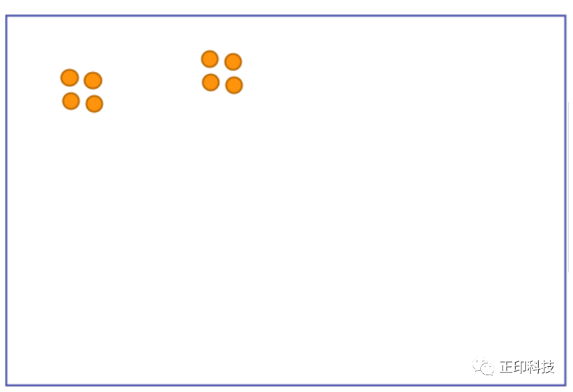
(Figure 9. Example of multi-target grouping)
Verification test options(pros and cons)
The three different calibration model tests proposed (reprojection test, projection test, triangulation test), no matter which calibration verification test you choose, you should always run the image coordinate system test, because the team performing the verification may use a different one from the calibration team The coordinate system.
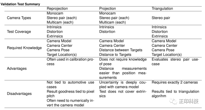
(Pros and cons of three different calibration model tests)
Conclusion
This article describes four geometric calibration verification tests: one for the image coordinate system, and three for various combinations of calibration parameters.
Contact: sales@colorspace.com.cn
Phone: 15817270587
Tel: 400-886-3881(周一至周五 9:00~18:00)
Email: sales@colorspace.com.cn
Add: South Building #2-1101, Lv Di Qi Hang Office Building, Hou Sha Yu, Shun Yi District, Beijing, China